Required Materials
- 1 length of 1/2 inch Schedule 40 PVC pipe, approximately 3 feet (91 cm) long (for the boom)
- 2 feet (61 cm) of 1/2 inch Schedule 40 PVC pipe (for element supports)
- Approximately 12 feet (3.7 meters) of steel measuring tape (for elements)
- Approximately 10 feet (3 meters) of thin coaxial cable (e.g., RG-174 or similar) with an SMA or BNC connector on one end (to match your radio)
- Small piece of stranded wire (e.g., speaker wire, about 6 inches/15 cm)
- Zip ties (cable ties)
- Electrical tape
- Solder
Tools Needed
Step 1: Cut the main PVC pipe for the boom to 3 feet (91 cm) in length. This will serve as your antenna’s central support.
Step 2: Cut four small pieces of PVC pipe, each about 2 inches (5 cm) long, from the additional PVC pipe. These will act as spacers for the elements.
Step 3: Mark the element positions on your 3-foot boom: Start about 3 inches (7.5 cm) from one end. This will be the Reflector position. Measure 14.5 inches (37 cm) from the Reflector mark and make a mark for the Driven Element. Measure another 14.5 inches (37 cm) from the Driven Element mark and make a mark for the Director.
Step 4: Cut the steel measuring tape into three distinct lengths for your elements, ensuring the shiny, conductive side is used for the antenna: Reflector (41.25 inches / 105 cm), Driven Element (38 inches / 96.5 cm), and Director (36.5 inches / 92.7 cm). Be careful as the edges can be sharp.
Step 5: For the Driven Element, find its exact center and carefully cut or score the measuring tape across the width, creating a small non-conductive gap of about 1/4 inch (0.6 cm) at the center. This creates two halves for feeding.
Step 6: Attach the 2-inch PVC spacers to the boom at the marked positions using strong zip ties. Orient them so the elements will pass through them perpendicular to the boom. Ensure they are securely tightened.
Step 7: Thread each cut measuring tape element through its corresponding PVC spacer. Position each element so its center aligns with the center of the boom. Secure each element firmly to the spacer and boom using additional zip ties and electrical tape. Ensure the elements are perfectly straight and perpendicular to the boom.
Step 8: Take the 6-inch piece of stranded wire. Strip about 1/2 inch (1.2 cm) of insulation from both ends. Solder one end to one side of the split Driven Element and the other end to the other side of the split Driven Element, forming a small loop across the gap.
Step 9: Prepare your coaxial cable: Strip the outer jacket back about 1 inch (2.5 cm) from the end. Carefully separate the braid (shield) from the center conductor. Strip about 1/2 inch (1.2 cm) of insulation from the center conductor.
Step 10: Solder the center conductor of the coaxial cable to one half of the Driven Element (where the stranded wire loop connects). Solder the braided shield of the coaxial cable to the other half of the Driven Element. Ensure good, solid solder joints.
Step 11: Secure the coaxial cable along the boom with electrical tape or zip ties to provide strain relief and prevent it from interfering with the antenna’s radiation pattern. Make sure no bare wires are touching each other or the boom at unintended points.
Step 12: Perform a final visual inspection to ensure all elements are straight, securely attached, and correctly spaced. Check all electrical connections.
Pro Tip
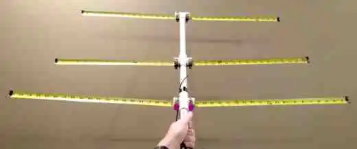
For best reception, point the Director (the shortest element, marked ‘Front’ in the diagram) towards the signal source. The Yagi antenna is highly directional. For optimal performance, especially when transmitting, a proper SWR meter should be used to tune the element lengths slightly for the desired frequency range. You may need to trim small amounts from the element tips or adjust spacing for the lowest SWR. Keep the antenna away from large metallic objects or the ground during operation to minimize interference with its radiation pattern.