Hello fellow hams! Whether you’re a newly licensed operator eager to get on the HF bands or a seasoned veteran looking for a simple, effective multi-band antenna solution, the fan dipole is a fantastic project. It allows you to operate on multiple bands using a single coaxial feedline, saving space and complexity compared to multiple individual antennas.
This guide will walk you through building a fan dipole for the popular 10, 15, 20, and 40-meter bands. We’ll cover the theory, calculations, materials, construction, and the crucial tuning process.
Why Build a Fan Dipole?
- Multi-Band Operation: Access multiple bands with one antenna and one feedline.
- Simplicity: Relatively easy to construct compared to complex beams or verticals.
- Cost-Effective: Uses common, readily available materials.
- Good Performance: Offers standard dipole performance on each band it’s designed for.
- Great Learning Project: Understand antenna theory and tuning hands-on.
The Basic Principle
A fan dipole consists of multiple dipole elements cut for different bands, all connected in parallel to the same feed point. Imagine several individual dipoles sharing the central connection point but “fanning” out from each other. This separation helps minimize interaction between the elements, although some interaction (and re-tuning) is inevitable.
The Magic Formula: Calculating Element Lengths
The starting point for any dipole is the basic half-wavelength formula. In amateur radio, we typically use a shortened version that accounts for the “velocity factor” of wire and “end effect” (capacitance at the element ends).
The most common formula for a half-wave dipole’s approximate length in feet is:
Length (feet) = 468 / Frequency (MHz)
Each leg of the dipole will be half of this total length.
For metric users, the formula is approximately:
Length (meters) = 142.6 / Frequency (MHz)
Important: These formulas provide a starting point. The final length will always need to be adjusted (usually shortened) during the tuning process based on your specific installation height, surroundings, wire type, and insulators used. Always cut your wires longer than the calculated length!
Calculating Our Starting Lengths
Let’s calculate the initial lengths for our target bands. We’ll choose frequencies near the middle of the popular segments (like SSB or CW) for each band. You can adjust these based on where you prefer to operate.
-
40 Meters (e.g., 7.150 MHz):
- Total Length (ft) = 468 / 7.150 ≈ 65.45 feet
- Length per Leg (ft) ≈ 32.73 feet
- (Metric: Total ≈ 142.6 / 7.150 ≈ 19.94 meters; Leg ≈ 9.97 meters)
- Start with: ~34 feet per leg (or ~10.3 meters)
-
20 Meters (e.g., 14.175 MHz):
- Total Length (ft) = 468 / 14.175 ≈ 33.01 feet
- Length per Leg (ft) ≈ 16.51 feet
- (Metric: Total ≈ 142.6 / 14.175 ≈ 10.06 meters; Leg ≈ 5.03 meters)
- Start with: ~17 feet per leg (or ~5.2 meters)
-
15 Meters (e.g., 21.225 MHz):
- Total Length (ft) = 468 / 21.225 ≈ 22.05 feet
- Length per Leg (ft) ≈ 11.03 feet
- (Metric: Total ≈ 142.6 / 21.225 ≈ 6.72 meters; Leg ≈ 3.36 meters)
- Start with: ~11.5 feet per leg (or ~3.5 meters)
-
10 Meters (e.g., 28.400 MHz):
- Total Length (ft) = 468 / 28.400 ≈ 16.48 feet
- Length per Leg (ft) ≈ 8.24 feet
- (Metric: Total ≈ 142.6 / 28.400 ≈ 5.02 meters; Leg ≈ 2.51 meters)
- Start with: ~8.75 feet per leg (or ~2.7 meters)
Materials You’ll Need:
- Antenna Wire: Insulated stranded copper wire (e.g., #14 AWG) is durable and easy to work with. Calculate the total length needed based on your starting lengths, adding extra for tuning and connections.
- Center Insulator/Feed Point: A commercial center insulator with a SO-239 connector and ideally an integrated 1:1 Balun (Balun = Balanced to Unbalanced). A 1:1 current balun is highly recommended to prevent feedline radiation and improve the antenna’s radiation pattern.
- End Insulators: At least 8 end insulators (dog bone or similar).
- Coaxial Cable: Good quality 50-ohm coax (RG-8X, RG-213, LMR-400) with appropriate connectors (PL-259 for the antenna end). Length depends on your run to the shack.
- Support Rope: UV-resistant rope (e.g., Dacron) to support the antenna ends.
- Spacers (Optional but Recommended): Non-conductive material (PVC pipe sections, plexiglass strips, plastic cutting board pieces) to keep the different band elements separated along their length. This improves performance and reduces interaction.
- Hardware: Stainless steel screws, nuts, washers, and crimp lugs for connecting wires to the feed point.
- Tools: Wire cutters, wire strippers, soldering iron & solder (optional, but good for connections), measuring tape, knife, drill (for spacers), wrenches/pliers.
- Tuning Equipment: An Antenna Analyzer or an SWR meter and your transmitter (used at low power).
Construction Steps
- Prepare the Center Feed Point: If using a commercial center insulator/balun, ensure it’s ready for connections. If building your own, construct a weatherproof box with an SO-239 connector and connection points for the antenna wires. A 1:1 balun is strongly recommended here.
- Cut the Wires: Measure and cut four pairs of wires based on your calculated starting lengths (the longer ones!). Label each pair clearly (e.g., “40m L”, “40m R”, “20m L”, etc.). Remember: LONGER is better – you can always trim, but you can’t easily add length back.
- Attach Wires to Feed Point: Securely attach one wire from each pair to one side of the center feed point terminals, and the other wire from each pair to the other side. Use crimp lugs and stainless steel hardware. Ensure good electrical contact. Solder lugs if possible for long-term reliability. Typically, the longest element (40m) is placed “on top” or closest to the feed point connector body, with progressively shorter elements fanned out below or beside it.
- Create the Fan: Arrange the wires so they spread out from the center feed point. They should not touch each other except at the feed point.
- Using Spacers: A few feet out from the center, and perhaps again further down, use your non-conductive spacers to maintain separation between the different element pairs. Drill holes in the spacers and run the wires through, securing them loosely (allowing for sliding during tuning). Aim for at least 6-12 inches (15-30 cm) of separation if possible.
- Without Spacers: Gravity and careful tensioning can create some separation, but performance and tuning will be more predictable with spacers.
- Attach End Insulators: Attach an end insulator to the far end of each wire (8 insulators total). Create a small loop in the wire, pass it through the insulator, and secure it back onto itself (a good mechanical connection is sufficient, soldering isn’t usually needed here).
- Attach Support Ropes: Tie your UV-resistant support ropes to the end insulators.
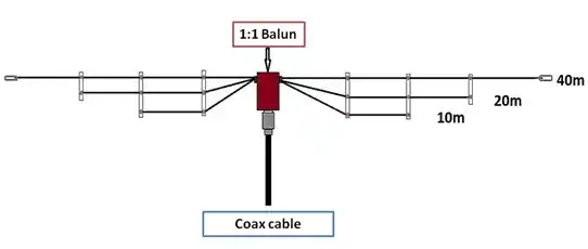
Diagram Concept
Imagine the center feed point/balun suspended in the air.
- The coaxial cable hangs down from the bottom.
- Connected to the two terminals of the feed point are four pairs of wires.
- Pair 1 (40m): The longest wires, extending outwards horizontally or as an inverted V.
- Pair 2 (20m): Shorter wires, connected to the same terminals, fanning out slightly below or beside the 40m wires.
- Pair 3 (15m): Even shorter, fanning out below/beside the 20m wires.
- Pair 4 (10m): The shortest, fanning out below/beside the 15m wires.
- Spacers (if used) are placed at intervals along the lengths to keep the parallel wires separated.
- End insulators are attached to the far end of each wire, with support ropes going to your anchor points.
(Visual Description of Finished Product): When installed, it looks like several wire dipoles draped one below the other, all originating from the central feed point box. The wires spread apart like the ribs of a fan. From a distance, it might just look like a single, slightly thicker wire antenna, depending on the separation achieved.
Installation and THE CRUCIAL Tuning Process
- Safety First! Never install antennas near power lines. Be careful when working at heights. Ensure supports are strong enough.
- Raise the Antenna: Hoist the antenna to its intended operating height. Higher is generally better for HF performance, especially for lower bands like 40m. Try to keep the antenna away from large metal objects (gutters, towers, etc.). An inverted-V configuration (center high, ends lower) is common and works well.
- Connect Analyzer/SWR Meter: Connect your antenna analyzer or SWR meter and transmitter (set to low power!) to the coaxial feedline.
- Tune LOWEST Band First (40m):
- Check the SWR or resonant frequency on the 40-meter band using your analyzer or SWR meter across the band.
- If the frequency of minimum SWR is lower than your target frequency, the 40m wires are too long.
- Carefully lower the antenna (or just the ends if accessible). Trim a small amount (e.g., 2-3 inches / 5-8 cm) from each 40m leg.
- Re-hoist the antenna and check the SWR/resonant frequency again.
- Repeat this process iteratively, trimming small amounts until the minimum SWR is at your desired frequency within the 40m band. Patience is key!
- Tune Next Band (20m): Now, check the SWR on the 20-meter band. Adjust the 20-meter wires using the same iterative trimming process until resonant.
- Tune 15m and 10m: Repeat the tuning process for the 15m wires and then the 10m wires.
- Re-Check Lower Bands: Important! Adjusting the shorter elements can slightly affect the tuning of the longer elements. After tuning 10m, go back and re-check the SWR on 40m, 20m, and 15m. You may need to make very small final adjustments. Tuning often involves going back and forth between bands. The interaction is usually: adjusting shorter wires affects longer wires less than adjusting longer wires affects shorter ones. This is why we start with the longest (40m).
- Finalize Connections: Once tuned, ensure all connections are secure and weatherproof the center feed point and coax connection. Trim any excess tuning “pigtails” at the ends.
Tips for Success
- Safety: Cannot emphasize this enough. Power lines, heights, RF exposure (use low power for tuning).
- Start Long: Always cut wires longer than calculated.
- Tune Lowest First: Start with the longest elements (lowest frequency band).
- Small Adjustments: Trim small lengths during tuning. It’s easy to cut more, impossible to add back easily.
- Use a Balun: A 1:1 current balun at the feed point is highly recommended for best performance.
- Symmetry: Try to keep the legs symmetrical and the antenna reasonably balanced.
- Environment Matters: Height above ground and nearby objects will affect tuning. The antenna will perform differently once raised to its final height compared to tuning it near the ground. Tune it at its final height if possible, or be prepared for shifts.
- Patience: Antenna tuning requires patience. Don’t get discouraged if it takes a few tries.
Conclusion
Building a 10-15-20-40 meter fan dipole is a rewarding project that yields a versatile and effective antenna. It requires careful measurement, methodical tuning, and a bit of patience, but the result is access to four popular HF bands with a single feedline. Get out there, gather your materials, and enjoy the process of building and using your own multi-band antenna!
Happy building and 73!